Network Function as a Service

19.07.21 09:32 AM - By Shiv

Network Function as a Service

SummaryThe current set of network functions are part of, or dependent on a unix/linux kernel. Examples of such functions are IPsec, firewalls, proxies, and so on. Once moved to the cloud, they can form a Network Function as a Service (NFaaS), and we can chain together multiple individual services. Kubernetes is the platform of choice for moving applications to the cloud. This blog identifies the gaps, and proposes solutions - both in the platform (Kubernetes), and in the network functions themselves -  for the cloud transformation of the network functions.

Network Functions

Kubernetes is the platform of choice when we move applications to the cloud. There are different types of application that can use Kubernetes. One type is the traditional web server, database applications. There are quite a few abstractions in Kubernetes provided for these applications - service, deployment, statefulset, persistent volumes, and so on.

Another class of applications, popularly referred to as network functions, needs high performance networking, and HA. One example of this class of applications is the telco cloud [1]. The next generation of telco cloud is moving to containers, microservices, and Kubernetes. Another example of  applications that need high performance networking are part of the SASE [2] architecture - specifically, the cloud firewall, CASB, and secure web gateway.  

Currently, many of these applications run on specialized hardware - with network processors, hardware accelerators, and so on [3]. The version of the applications running on general purpose hardware typically use a unix/linux kernel stack [4].  This is shown in Figure 1.

Figure 1: Traditional Network Function Architecture

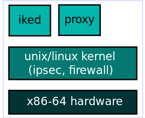
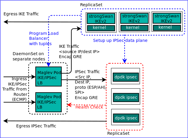
The data plane is the unix/linux kernel which does the IPsec encryption/decryption. The stateful firewall processsing is  done in the kernel using iptables/NETFILTER framework. The IKE processing is done in userspace, and is shown as iked (IKE daemon) in the figure. Strongswan IKEv2 daemon is a popular choice. The proxies for the various applications are also present in userspace.


The cloud versions of these network functions are also referred to as cloud-native network functions (CNF).

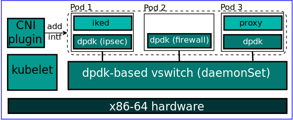
Network Functions in the cloud: High performance CNI plugin

When we port network functions to the Kubernetes world, the transformation can be done in two discrete steps. These two discrete steps are there to address two separate issues. The first issue is that popular Kubernetes plugins such as calico, flannel, etc., use the linux kernel network stack. There is a version of calico with VPP [5], but it is in tech preview. Processing the  network flows in the kernel introduces latencies, and is not able to keep with NIC speeds [6], so the solution is to bypass the kernel, and the popular Intel DPDK  provides the necessary components to achieve userspace networking.

So, the first step in the transformation is to use Kubernetes CNI plugins such as OpenVswitch-dpdk or, VPP [7] that are based on DPDK . This will enable the pods to talk to each other on a high performance network.

Figure 2: Pods using high performance CNI plugin
The CNI plugin basically creates a DPDK-based virtual switch on each node using a privileged daemonset. Each network function is in a pod of its own, and hooks into this virtual switch. Pod 1 in Figure 1 provides IKE/IPsec functions, pod 2 provides the firewall function, and so on. This approach has the benefit that existing network functions which are using the linux kernel can be ported to the container world easily.

The main issue with this approach is that with the actual network processing occurs inside the pods, and the pods are running the linux kernel.  So, there is still a kernel in the packet processing path, and this reduces the network throughput.

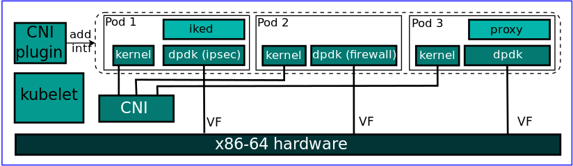
Network Functions in the cloud: High performance application network stack

The solution to this is to refactor the application to use a high performance network stack. Essentially, the pods should also use a DPDK based network stack. This application can be then be used in two configurations. The first configuration consists of pods with a DPDK network stack talking to each other over a DPDK based CNI plugin. This is shown in Figure 3 below.


Figure 3: Application network stack and CNI plugin based on DPDK
Pod 1 in Figure 3 consists of IPsec processing being done in the DPDK-based network stack, and an IKE daemon modified to use the DPDK-based network stack. Pod 2 consists of the firewall implemented as part of a DPDK-based stack, and in pod 3 the proxy is modified to used the DPDK-based stack. This is huge effort from a development point of view since the userspace daemons need to be modifed to use the DPDK-based TCP stack [8]. We will coming to this issue in a later section.

The advantage of this approach is that the Kubernetes abstractions of the CNI plugin such as network policy, services can still be used. Also, this architecture can be used to run as a computing PaaS. Third party network functions can run inside the pods, and the service provider can provide policy in the Kubernetes plugin to support the third party network functions.

The issue with this approach is that we have DPDK running in the plugin, and inside the pods. Each DPDK instance runs an infinite loop polling a port for incoming packets [9]. As, the number of DPDK instances increases, the number of vcores needed correspondingly increases.  The second configuration addresses this issue of increased vcores being needed.

Network Function as a Service (NFaaS)

This configuration eliminates the DPDK-based vswitch and is shown in Figure 4.  The DPDK-based pod directly uses the network interface on the node.

This scheme requires two interfaces, one which the DPDK-based stack uses, and another which the Kubernetes CNI plugin uses.  The CNI plugin can be a non-DPDK-based plugin. The benefit of this approach is that there is one less  DPDK instance handling the network flows, and hence the corresponding reduction in CPU resource needed. This solution can be used if the service provider is providing Network Function as a service. Hence, this solution is called Network Function as a Service (NFaaS). 

There are other references to NFaaS [10], but those are more for a VM based service, rather than container based service.

There is no third-party application code running here. All the code is controlled by the service provider, and hence the DPDK-based pods can directly access the VM network interface ports. Examples of such an architecture would be cloudflare [11].

Figure 4: Network Function as a Service
We can provide the same facilities as the Kubernetes plugin, but all this will need to be implemented as custom resources or controllers. We can provide features for multi-tenancy, network policy, and other features.

Please note since a pod directly takes a single interface, we need to have SR-IOV enabled NICs in case multiple NF pods are to placed on a given node. Hence, the figure shows each pod associated with a VF on the node.

We will be focusing on the this solution from now on in the blog.

Gaps in Kubernetes support for NFaaS

The current Kubernetes abstractions are more oriented towards compute rather than networking. Let us go through the areas of improvement if we want to support an NFaaS on Kubernetes.

Multi-tenancy:

The current way multi-tenancy is provided is using cluster, namespace, node,  pod,  and container [12]. This approach is good enough for computing service, but not  for a networking service.


Consider a network function container provisioned using the above multi-tenancy scheme.  A container is the smallest granularity in the above scheme.  Although the k8s API allows us to specify fractions of the CPU, we need to provide multiples of cores to the network function to provide high performance [13].  So, this container would be assigned using some vcores and would be serving traffic associated with one tenant. Now, if the tenant traffic is less than the capacity of the container, then utilisation is sub-optimal. Hence, to improve utilisation, we need to allow a network function container to handle flows associated with multiple tenants.


We can use cgroups that are subsets of the container runtime (CRI) defined cgroups to ensure resource isolation between the tenants in a given container.  We can have multiple threads - one per each tenant - in the data plane, and associate each of these threads with different cgroups. Each packet needs a tenantId in its meta-header, so that the required thread in the data plane will handle the packet, and the correct resource accounting for the cgroup will be done.

Load Balancing:

We need to provide load balancing between various network function pods that are offering a service. Since, we are bypassing the Kubernetes CNI, we need to build a separate load balancing component.


Currently, the load balancers like iptables, IPVS are part of the linux kernel, or utilize the linux kernel. Now, we need a load balancer which can be made part of the DPDK-based network stack. Maglev [14][15] is a load balancer used by Google for its Kubernetes Network Load Balancer service. Maglev uses consistent hashing to balance load evenly across its backend pods. It prioritises load balancing over disruption and tries to balancer load as evenly as possible among the backends.

Figure 5: NF Pods access db updated by Maglev Pod

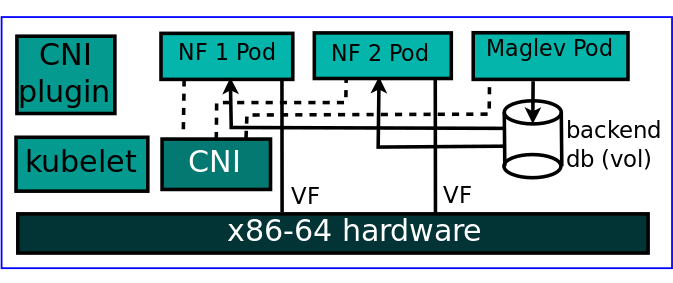
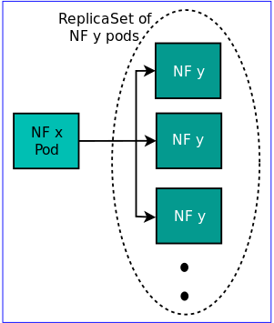
The load balancer db is available on all nodes. This NF x selects a backend NF y using consistent hashing. Each backend is a replicaSet in the Kubernetes world, and not a deployment. The reason being that to create another version of the backend, we need to sync additional state to the new version. For that a deployment is not sufficient as mentioned in the pod state section.


Figure 6: Load balancing between members of replicaSet

Service Chaining:

Service chaining basically can be used to set policy as to the paths that a packet can take within a network. Service chain can be represented by a graph of of interconnected network function nodes, and thus represents the path that a packet can take. 


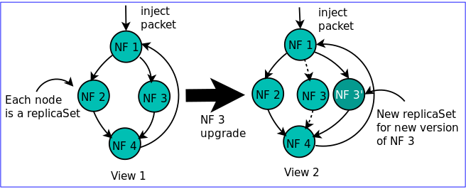
Our solution for a service chain is a versioned graph, and each packet has a corresponding position within this graph. So, each packet meta-header has a graph view id,. The next NF will be determined by the forwarding code.  


Each NF node is a replicaSet, and a service chain is a graph of interconnected replicaSets. In that sense, a service chain is a generalization of the Kubernetes deployment abstranction.


The load balancer pod will maintain the status of only those backends as is required by the graph view. The load balancer will provide the backend for the next NF, and the packet will be sent along to that node.


Figure 6: Network Function upgrade
Multiple versions are needed in case we are modifying a graph. This change will be done as a transcation. The previous version of the graph will be maintained as long as there packets present in that graph version. Please note that HA is not provided using service chaining. Service chaining represents purely the functional packets processing needed to be done by a node. So, using multiple versions of a graph, we can do upgrades, rollbacks, canary testing, and so on of the network functions.

One advantage of this approach is that we can provision the required resources by examining the graphs of the individual tenants, and the likely breakup of the packets within the various paths.

When a flow enters the NFaaS system, the tenant associated with the flow is determined, and the  view id associated with the tenant is identified and filled in the packet meta-header. The packet is then injected into the first NF of the graph. The packet traverses the graph associated with the view id. It is possible that in the middle of a graph, the packet is determined to be some other packet type, and the packet might be injected into another view. 

Each flow needs the following iDs - tenantId (3B), viewId (1B).

Pod State:

Let us take the example of a deployment in Kubernetes. Here it is assumed that the pods are stateless, and the state is represented in a separate db pod. An upgrade can occur simply by creating a new pod, redirecting traffic to the new pod, and deleting the old pod.


If we map a network function to a pod, then an upgrade of the network function will result in the creation of a new pod, and the traffic needs to be diverted to the new pod. Now, for the new pod to handle the traffic, it might some state associated with the flow - some sequence number, or parameters associated with flow needs to be available for it to start processing a flow - depending on the protocol involved.


This flow-related data needs to picked from the old pod, and made available to the new pod. So, the key point is network function pods cannot be stateless. And we need abstractions to deal with pod state in case of upgrades, and HA.


We can create a Kubernetes operator to define a stateful pod. This stateful pod can point to a replicaSet, and members of this replicaSet can share in-memory state. The state needs to be in-memory since this state needs to be accessed by the data plane, and the access needs to be fast.

Decomposing the Network Functions

With gaps in the platform identified, we can move onto identifying issues with the network functions themselves. For a network function to benefit from cloud technologies, we need to move to a microservices architecture. Microservices architecture principles involve decomposing an monolithic application into multiple, smaller, independent services.  The benefits of microservices include heterogeneity of technology, ease of deployment, and scaling [17].

For example, consider the IPsec network function. We can breakdown the IPsec function into a control plane service, and a data plane service as shown in Figure 7 below. For the control plane, we can utilize the Strongswan IKEv2 daemon. It is a feature-rich daemon, and runs on a linux kernel. The data plane can be a DPDK-based implementation for high performance.

Figure 7: Separate control and data plane for IPSec processing
The Maglev pods direct the IKE traffic to IKE pods. The IKE pods are part of a replicaset. The IKE pods program the data plane pods with the required session details to setup a IPsec session. The Maglev pods encapsulate the IKE/IPsec traffic in GRE and ship them to the IKE, data plane pods. The replies are sent back directly, and bypass the Maglev pods. The Maglev pods periodically check the health of the backends, and are themsleves part of a daemonset and located on a separate set of nodes which are served traffic that is ECMP load balanced from the router.

Benefits:

This approach will have reduced risk, as compared to the IKE based on a DPDK-based TCP stack as shown in Figure 3/Figure 4, as we are using a tried and tested control plane implementation. Thus, we can mix and match multiple technologies (user-space application using kernel network stack and a DPDK-based data plane) for a single network function.


Microservices helps in deployment, as only required microservice - either Maglev, control plane, or data plane - needs to be upgraded rather than a bigger monolithic application.


Also, now that the control plane, and data plane are separated, they can be scaled independently.  This means that we can scale only those services which limit the network function performance, and not the entire monolithic application. For example, to increase IPsec network function capacity, we would mostly need to scale only the data plane service  since most of the packet processing is done by the data plane pods. 

Related Work:

A similar architecture was proposed by fd.io called Kiknos [18] that is slightly different. There are no load balancer pods sitting between the router, and the data plane pods, and the data plane pods themselves punt the control plane traffic to the IKE pods.


The Kiknos approach has certain implications when the number of backends changes dues to failures, or additions. In Kiknos, in case the number of backends changes, then the ECMP router will send the IPsec traffic to another data plane pod. The new pod gets the IPsec session details from a separate datastore that is shared by the data plane pods. In our proposed implementation, the Maglev pods maintains a connection table which is sticky. Even if the number of data plane pods change, the Maglev pods will refer to the connection table before attempting a consistent hash. So, the Maglev pods maintain the state, and we avoid a data store that can be a potential bottlneck.


Similarly, for an a IKE/IPSec SA rekey, in our proposed architecture, the IKE control plane programs the Maglev pods with the required tuples which use the new SA, so that the control plane / data plane pods do not change due to change in hash of the SA tuples.

In case the membership of the Maglev replicaset changes (due to failures, upgrades, or additions), then the router will send the IKE/IPsec traffic to a different Maglev pod. To handle this case, we can use the stateful pod proposed in a previous section to lazily update connection information to all the members of the Maglev replicaset. In this way, we can ensure that all connections which were synced up to the last update will be retained.

Conclusion, Further Work

The current set of network functions can be moved to the cloud in two discrete steps. The first step is to use a high performance CNI plugin, and the next step is to refactor the network functions to use a high performance network stack. Some gaps in the Kubernetes support for network functions were identified, and moving to a microservices architecture for the network functions enables us to select the best components for a given service, and potentially enables cloud scale and ease of maintenance.

It is proposed to prototype the IPSec network function microservices, Kubernetes platform modifications as described above, and the results will be presented in future blogs posts.

References


Shiv